
⭐ Featured in Superhive Fresh Finds (March 2026)
When Perspective Needs to Be Right.
SightLine³ gives you structural control over camera matching — so your scenes stay grounded in real-world geometry.
• Accurate perspective matching
• Multi-camera workflows
• Controlled refinements with Solve Lock
• Built on the TwinRay™ System
For Artists Who Need Perspective to Be Right
Perspective matching isn’t cosmetic — it’s structural.
When the camera is wrong:
• Scale drifts
• Proportions feel off
• Modeling becomes guesswork
• Compositing falls apart
Architectural artists.
Product visualizers.
Set extensions.
Photogrammetry cleanup.
Concept refinement.
If you place real geometry into a photographed world, the camera must be believable.
SightLine³ is built for artists who require structural accuracy.
Not approximation.
Not “close enough.”
Structure first.
Confidence second.
Speed follows.
Watch SightLine³ in Action
Structured camera solving is best demonstrated — not described.
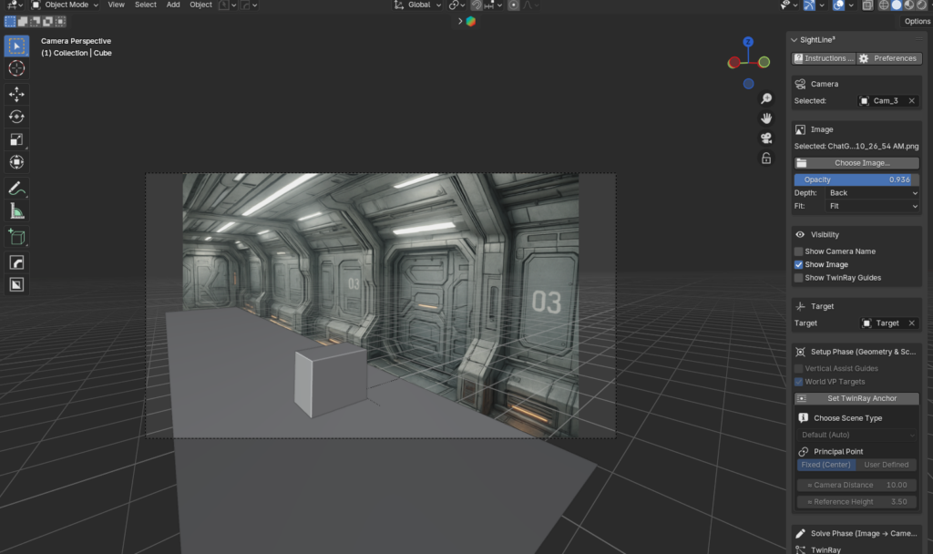
Corridor Camera Solve
A full perspective solve inside a structured corridor environment.
The corridor provides strong linear convergence across X, Y, and Z axes — ideal for demonstrating how TwinRay™ establishes measurable, repeatable camera alignment.
• Accurate perspective match
• Controlled refinements
• Solve Lock workflow
• Structurally grounded result
Watch on YouTube:

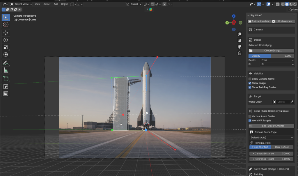
5 Image Solve Proof
Five separate camera solves.
Five different image positions and rotations.
One consistent structural system.
Each solve is validated using a real-scale 2-meter cube to demonstrate repeatable alignment across multiple viewpoints.
This is not approximation.
This is structural consistency.
Watch on YouTube:

The TwinRay™ System
TwinRay is a paired-ray geometric constraint system.
It defines perspective through hinged ray relationships along structured axes.
Each axis is constrained by explicit paired rays — not inferred vanishing lines.
This creates measurable convergence and repeatable solves.
TwinRay is responsible for:
• Defining perspective geometry
• Establishing convergence relationships
• Maintaining vertical structure
• Producing consistent re-solves
You are not adjusting visuals until they appear correct.
You are defining geometric relationships.
Control follows structure.
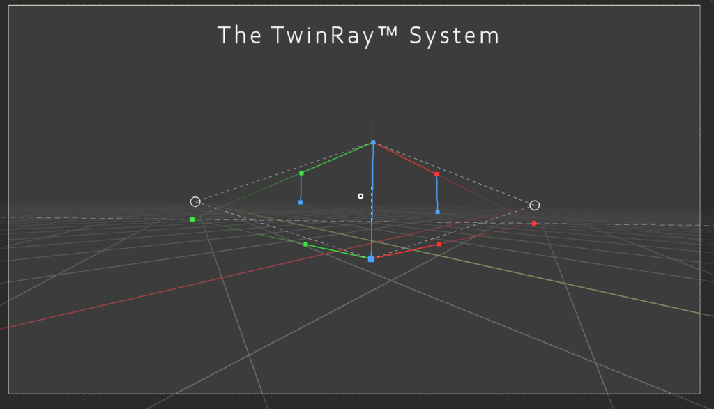
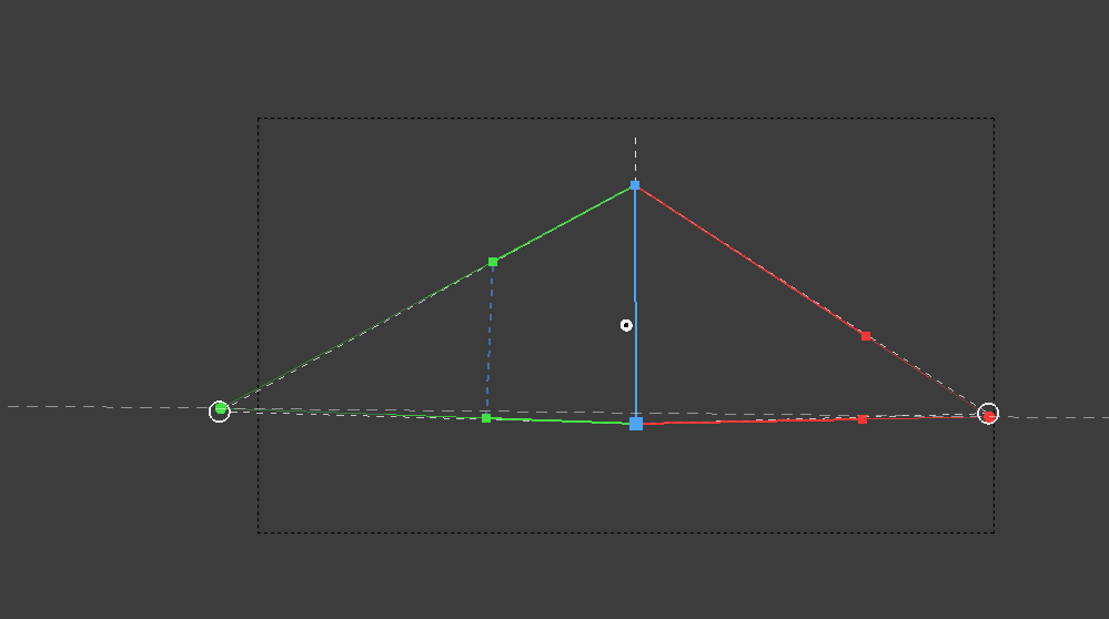
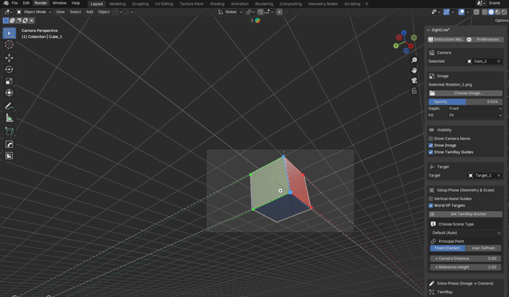
Understanding the TwinRay™ Structure
Center Vertical (Blue Line)
This is the Z Axis Constraint.
The larger cube represents ZBot — the primary TwinRay anchor point.
The smaller cube above represents ZTop.
The distance between ZBot and ZTop defines TwinRay’s reference height measurement unit.
Green TwinRay (Left Axis Pair)
These paired rays define one horizontal convergence constraint.
Unlike a single guide line, TwinRay uses a hinged pair to establish measurable, repeatable structure.
Red TwinRay (Right Axis Pair)
Mirrors the green axis pair.
Together, these paired constraints define horizontal perspective relationships.
Vertical Assist Guides
The shorter blue vertical segments connected to the top fans represent optional Vertical Assist constraints.
These provide additional vertical reference reinforcement when strong architectural verticals are present in the image.
They do not redefine the primary Z Axis Constraint.
They strengthen vertical confidence during solving.
Vertical Assist Guides improve stability in scenes where precise vertical alignment is critical.
TwinRay Vanishing Points
The circular markers at the outer ends represent TwinRay’s derived convergence targets — generated from paired ray relationships, not assumed vanishing lines.
World VP Targets (Dotted Lines)
The dashed lines represent world-aligned reference indicators.
These assist in validation and diagnostic confirmation but do not override TwinRay’s geometric constraints.
Structured Convergence
All constraints meet in a controlled, measurable relationship.
This is not freeform guide alignment — it is structured geometry.
Workflow Overview
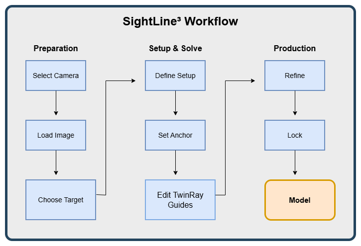
Interface Overview
1️⃣ Instructions Manual / Preferences
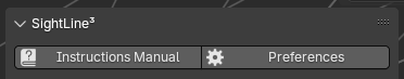
Instant access to guidance and configuration.
Includes:
• Workflow explanations
• Modal behavior
• Interaction rules
• Practical usage notes
• One-click access to Preferences and official resources
Always available directly from the SightLine³ panel.
2️⃣ Camera
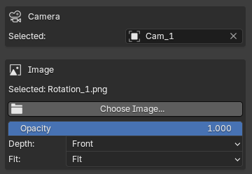
SightLine³ operates on standard Blender cameras.
You select which existing scene camera the tool controls.
Each camera maintains independent:
• TwinRay guides
• Solve state
• Refinement offsets
• Lock state
From the Camera section, you can:
• Add or change the camera’s background image
• Toggle image visibility
• Adjust image opacity
• Set image depth (Front or Rear)
• Adjust image Fit
These controls update Blender’s native camera properties directly from within SightLine³, streamlining workflow without introducing proprietary camera systems.
3️⃣ Visibility
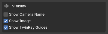
Controls viewport display elements.
• Show Camera Name
• Show Image
• Show TwinRay Guides
Workspace clarity without affecting solve data.
4️⃣ Target
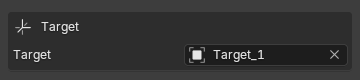
Defines the spatial grounding of the solve.
Options:
• World Origin
• Any object origin in the scene
The target determines where the solved camera aligns in 3D space.
Scene organization remains intact.
Setup Phase (Pre-Solve Parameters)

With camera and image active, this phase defines scene parameters that guide the solve.
This stage configures inputs — it does not move the camera.
Vertical Assist Guides
Adds additional vertical reference lines.
Used when architectural vertical reinforcement is helpful.
Optional.
World VP Targets
Displays world-based vanishing point indicators.
Used for validation and spatial confidence.
Optional.
Set TwinRay Anchor
Defines the primary ground reference.
With a single click on the image, you establish where your target (world origin or user-defined object) should align in 3D space.
Choose a clearly defined geometric point in the image:
• The ground corner of a building
• The corner edge of a sofa or table
• A floor-wall intersection
• The edge of a structure
• Any strong, stable geometric feature
This anchor is the starting point of every solve.
Selecting a precise and structurally meaningful point dramatically improves solve stability and confidence.
A strong anchor leads to a strong solve.
Scene Type (Lens Guidance)
Provides contextual focal range guidance.
Examples:
• Default (Auto)
• Street Scene
• Architectural
If the solved focal length falls outside the suggested range, a warning appears.
Advisory only.
Principal Point
Determines how the principal point is handled during solve.
Options:
• Automatic
• Manual
Affects camera alignment behavior.
Approximate Camera Distance
Provides a physical distance estimate from camera to anchor.
Used to improve spatial grounding.
Approximate Unit Height (ZBot → ZTop)
Defines a known vertical measurement in the image.
Establishes real-world scale for the solve.
Scale is derived from this relationship.
Solve Phase
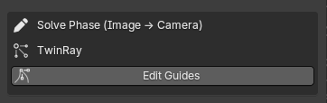
TwinRay guides become active.
Perspective constraints are defined directly in the viewport.
Edit TwinRay Guides
When active:
• Guides are interactive
• Other UI elements are temporarily disabled
• Focus is isolated
Exit with ESC or Right Mouse.
TwinRay relationships are updated during this process.
Post-Solve Refinement

Refinement tools apply controlled offsets after the initial solve.
They adjust the camera without redefining geometric constraints.
Camera Dollies
Modal post-solve camera offsets:
• Dolly X
• Dolly Y
• Dolly Z
• Zoom
These controls allow precise spatial alignment after the geometric solve is complete.
In real-world images, minor positional refinement is often required.
Most commonly:
• Dolly Z is used to align the target cleanly with ground level (ZBot), such as street height or floor plane.
• Zoom is used to fine-tune visual scale when the reference image and modeled geometry require slight framing alignment.
These adjustments do not redefine perspective geometry.
They operate as controlled post-solve transformations — preserving the integrity of the TwinRay solution while allowing practical production alignment.
Dolly Sensitivity
Controls offset responsiveness per pixel drag.
Lower = finer control
Higher = faster movement
Lens Micro Adjust
Allows focal length trimming in controlled increments.
Step options:
• 1.0 mm
• 0.5 mm
• 0.1 mm
Reset returns to solved baseline.
Roll Adjust (Degrees)
Applies controlled camera roll correction.
Does not alter TwinRay geometry.
Post-solve only.
Solve Lock

Prevents structural modifications after solving.
When enabled:

• TwinRay editing is disabled
• Setup controls are locked
• Refinements are preserved
• Guide removal is disabled
Designed for production stability.
Remove TwinRay Guides
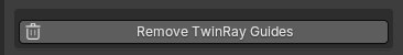
Clears solve data for the active camera.
Removes:
• Guides
• Anchor
• Solve state
Disabled while Solve Lock is active.
Developer Diagnostics
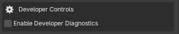
Advanced validation tools.
Hidden behind:
Enable Developer Diagnostics
Not required for normal operation.
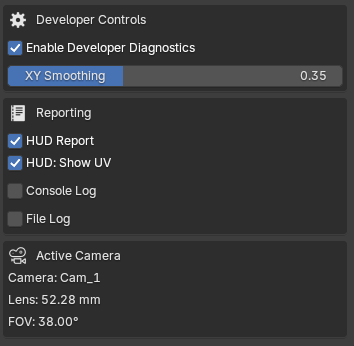
HUD Report
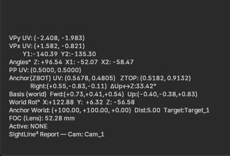
Displays live solver data:
• Vanishing point UVs
• Anchor coordinates
• Principal point
• Camera transforms
• Solved focal length
• Tool state
Viewport telemetry only.
Console Log
Outputs diagnostic data to Blender’s system console.
File Log
Writes diagnostic output to disk.
Active Camera Info
Displays:
• Camera name
• Lens (mm)
• Field of View (degrees)
Quick reference only.
When a Perfect Solve Is Not Possible

SightLine³ reconstructs the most physically plausible camera consistent with the image.
If the source image violates geometric consistency, a mathematically perfect match may not exist.
Examples of geometric conflict:
• Inconsistent parallel convergence
• Contradictory proportions
• Non-vertical verticals
In such cases, the solver produces the most believable result permitted by geometry.
This is not a limitation of the tool.
It is a limitation of the source image.
SightLine³ solves geometry.
It does not correct flawed imagery.
Real-World Solve Examples
The following examples demonstrate SightLine³ solving a range of scenarios — from simple geometric validation to complex production imagery.
Each solve is driven by structured TwinRay constraints.
The resulting camera aligns with measurable geometry inside Blender.
From controlled test cubes to real architectural and sci-fi environments, the principle remains the same:
Structure first.
Consistency second.
Speed follows.


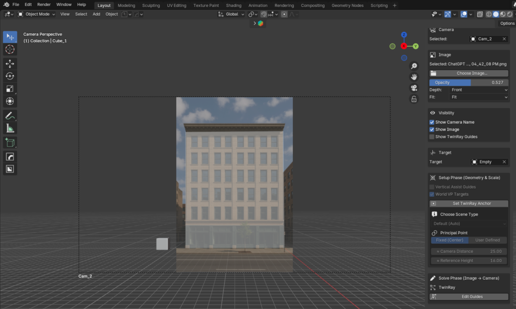
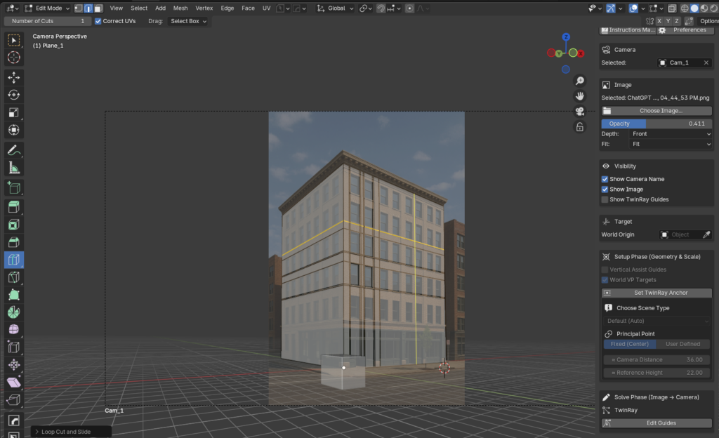
From Solve to Modeling
A perspective solve is only useful if it holds up during modeling.
Here, the reconstructed camera defines a consistent scale and orientation.
The building measures 22 meters in height — and the geometry built against it aligns accordingly.
SightLine³ doesn’t approximate perspective.
It establishes a camera you can trust when real dimensions matter.
Supported Platforms
Officially supported (tested):
- Windows 11 (64-bit)
- Blender 4.4 or newer
SightLine³ is currently developed and tested on Windows 11 using Blender 4.4+, and official support is limited to Windows 11 at this time. While Blender itself is cross-platform, support for additional operating systems may be evaluated in future updates.